 EN
EN

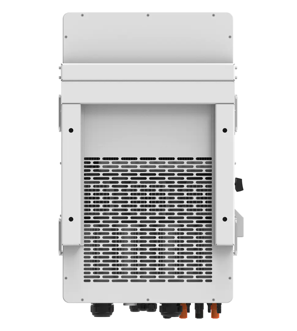
A battery inverter serves as the crucial bridge between stored DC power in batteries and the AC power required for household and commercial applications. The conversion process involves sophisticated electronic switching mechanisms that transform direct current into alternating current with precise voltage and frequency control. Understanding how this conversion occurs is essential for anyone working with renewable energy systems, backup power solutions, or off-grid installations where battery inverters play a central role in power management.
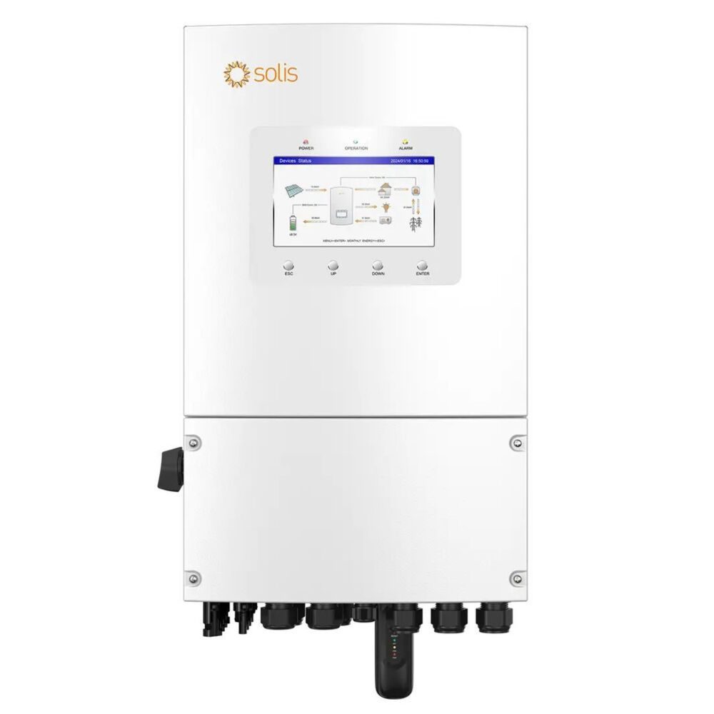
The DC to AC conversion process within a battery inverter relies on complex power electronics that manipulate electrical waveforms through rapid switching operations. Modern battery inverters utilize advanced semiconductor devices and control algorithms to produce clean, stable AC output that matches grid specifications. This conversion enables stored battery energy to power standard electrical equipment, making battery inverters indispensable components in solar energy systems, emergency backup configurations, and standalone power installations where reliable AC power delivery is required.
Understanding the Basic Conversion Mechanism
Electronic Switching Components
The heart of any battery inverter lies in its electronic switching components, primarily power MOSFETs or IGBTs that control the flow of DC current. These semiconductor switches operate at high frequencies, typically ranging from 20kHz to 100kHz, rapidly turning on and off to create the foundation for AC waveform generation. The battery inverter uses these switches in specific configurations, most commonly in full-bridge or half-bridge arrangements, to reverse the polarity of DC voltage at predetermined intervals.
Each switching cycle in a battery inverter involves precise timing control managed by sophisticated microcontrollers. The switches must activate and deactivate at exact moments to create the desired AC frequency, typically 50Hz or 60Hz depending on regional grid standards. The switching pattern determines both the frequency and the basic shape of the output waveform, with more complex switching sequences producing cleaner sine wave outputs from the battery inverter system.
Power losses during switching represent a critical design consideration for battery inverter efficiency. Modern designs incorporate advanced switch technologies with minimal on-resistance and fast switching speeds to reduce energy waste during the conversion process. The selection of appropriate switching components directly impacts the overall performance and reliability of the battery inverter under various load conditions.
Waveform Generation Process
The raw switching output from a battery inverter produces a square wave that requires significant modification to become usable AC power. This square wave contains the fundamental frequency component along with numerous harmonic frequencies that must be filtered to create a clean sine wave output. The initial square wave switching creates the basic alternating pattern, but advanced control techniques are necessary to shape this into high-quality AC power.
Pulse Width Modulation represents the most common technique used in modern battery inverters to generate quality AC waveforms. The PWM process varies the width of switching pulses while maintaining constant switching frequency, effectively controlling the average voltage delivered to the load. By continuously adjusting pulse widths according to a sine wave reference, the battery inverter creates an output that closely approximates pure sine wave characteristics.
Advanced battery inverters employ sophisticated PWM algorithms that minimize harmonic distortion while maximizing conversion efficiency. These algorithms consider real-time load conditions, battery voltage variations, and output requirements to optimize the switching pattern. The result is AC power with total harmonic distortion levels typically below 3%, suitable for sensitive electronic equipment and standard electrical appliances.
Voltage Transformation and Regulation
Step-Up Conversion Techniques
Battery systems typically operate at lower DC voltages than the required AC output voltage, necessitating voltage step-up capability within the battery inverter design. Most residential and commercial applications require 120V, 240V, or higher AC voltages, while battery banks commonly operate at 12V, 24V, 48V, or similar DC levels. The voltage transformation process involves either transformer-based or transformerless approaches, each with distinct advantages for specific applications.
Transformer-based battery inverters utilize magnetic coupling to achieve voltage step-up during the DC to AC conversion process. The transformer provides electrical isolation between the DC input and AC output while simultaneously adjusting voltage levels through turns ratio selection. High-frequency transformers in modern battery inverters enable compact designs while maintaining excellent voltage regulation and load isolation characteristics.
Transformerless battery inverters achieve voltage step-up through boost converter circuits integrated into the conversion topology. These designs eliminate the transformer weight and losses while maintaining high efficiency across varying load conditions. The battery inverter control system precisely regulates the boost conversion to maintain stable output voltage despite fluctuations in battery voltage as the energy storage system discharges or charges.
Output Voltage Regulation
Maintaining consistent output voltage represents a critical function of any battery inverter, especially as battery voltage naturally varies during charge and discharge cycles. Advanced regulation systems monitor output voltage continuously and adjust the conversion process to compensate for input voltage variations, load changes, and temperature effects. This regulation ensures that connected equipment receives stable power regardless of battery state of charge.
Feedback control loops in battery inverters compare actual output voltage with desired reference values, automatically adjusting switching parameters to maintain regulation accuracy within tight tolerances. These control systems typically maintain output voltage regulation within ±2% of nominal values across rated load ranges. The regulation speed must be fast enough to handle sudden load changes while remaining stable under all operating conditions.
Temperature compensation features in advanced battery inverters account for semiconductor and component variations that could affect output voltage stability. The control algorithms adjust switching parameters based on internal temperature measurements, ensuring consistent performance across wide temperature ranges. This temperature compensation becomes particularly important in outdoor installations where battery inverters experience significant environmental variations.
Filtering and Power Quality Enhancement
Output Filtering Systems
The switching action within a battery inverter generates high-frequency components that must be removed to produce clean AC power suitable for standard electrical equipment. Output filter circuits typically combine inductors and capacitors in carefully tuned arrangements that attenuate switching frequency harmonics while preserving the fundamental AC frequency. The filter design significantly impacts both power quality and conversion efficiency in the battery inverter system.
LC filter configurations represent the most common approach for battery inverter output filtering, utilizing the complementary characteristics of inductive and capacitive reactance. The inductor smooths current flow and reduces high-frequency current ripples, while the capacitor provides a low-impedance path for high-frequency voltage components. Proper filter component selection balances harmonic reduction against system size, cost, and efficiency considerations.
Multi-stage filtering in premium battery inverters provides superior harmonic attenuation through cascaded filter sections with different cutoff frequencies. Each filter stage targets specific frequency ranges, progressively cleaning the output waveform to achieve very low total harmonic distortion levels. The multi-stage approach allows optimization of each filter section for its specific frequency range, resulting in better overall performance than single-stage designs.
Power Quality Optimization
Modern battery inverters incorporate active power quality enhancement features that go beyond simple filtering to provide superior AC output characteristics. These features include active harmonic compensation, reactive power control, and voltage stability enhancement that improve power quality for connected loads. Advanced battery inverters can actually improve power quality compared to utility grid power in many situations.
Harmonic compensation algorithms in sophisticated battery inverters actively monitor output current and voltage waveforms, detecting harmonic distortion caused by nonlinear loads. The control system then adjusts the switching pattern to pre-distort the output waveform in a way that cancels load-generated harmonics. This active approach results in cleaner power delivery even when supplying distorting loads like electronic equipment or motor drives.
Power factor correction capabilities allow battery inverters to provide reactive power support for inductive loads while maintaining high efficiency. The inverter control system can adjust the phase relationship between output voltage and current to optimize power factor, reducing losses in connected equipment and improving overall system performance. This capability becomes particularly valuable in motor-driven applications where power factor improvement provides measurable benefits.
Control Systems and Protection Features
Microcontroller-Based Control
Advanced microcontrollers serve as the brain of modern battery inverters, managing all aspects of the DC to AC conversion process with precise timing and coordination. These digital control systems execute complex algorithms that optimize switching patterns, monitor system parameters, and coordinate protection functions in real-time. The microcontroller-based approach enables sophisticated features that would be impossible with analog control methods.
Real-time parameter monitoring within the battery inverter control system tracks input voltage, output voltage, current levels, frequency, temperature, and numerous other variables that affect conversion performance. The microcontroller processes this information continuously, making adjustments to maintain optimal operation under changing conditions. This monitoring capability also enables predictive maintenance features and system diagnostics that improve reliability.
Communication interfaces integrated into battery inverter control systems enable remote monitoring, configuration, and control capabilities through various protocols including RS485, CAN bus, Ethernet, and wireless connections. These interfaces allow integration with energy management systems, battery monitoring systems, and remote supervision platforms that optimize overall system performance and provide valuable operational data.
Comprehensive Protection Systems
Battery inverters incorporate multiple protection systems that safeguard both the inverter itself and connected equipment from various fault conditions. Overvoltage and undervoltage protection monitor input and output voltage levels, automatically shutting down the battery inverter if voltages exceed safe operating ranges. These protection functions prevent damage to sensitive components and ensure safe operation under abnormal conditions.
Overcurrent protection in battery inverters utilizes both hardware and software methods to detect excessive current flow that could damage switching components or connected loads. Fast-acting current limiting reduces output current when overloads are detected, while complete shutdown occurs if fault conditions persist. The protection system can distinguish between temporary overloads and permanent fault conditions, providing appropriate responses for each situation.
Thermal protection systems monitor critical component temperatures throughout the battery inverter, reducing power output or shutting down operation when thermal limits are approached. Temperature sensors placed at key locations provide early warning of thermal stress conditions, allowing protective action before component damage occurs. Advanced thermal management includes variable fan control and power derating algorithms that extend component life under high-temperature conditions.
FAQ
What is the typical efficiency of a battery inverter during DC to AC conversion?
Modern battery inverters typically achieve conversion efficiencies between 85% and 96%, with premium models reaching efficiencies above 95% at rated load conditions. The efficiency varies with load level, with peak efficiency usually occurring at 25% to 75% of rated capacity. Transformerless designs generally achieve higher efficiency than transformer-based units due to reduced magnetic losses, while the switching frequency and component quality significantly impact overall conversion efficiency.
How does switching frequency affect the performance of a battery inverter?
Higher switching frequencies in battery inverters enable smaller filter components and faster response to load changes, but also increase switching losses and electromagnetic interference. Most modern battery inverters operate between 20kHz and 100kHz, balancing component size, efficiency, and electromagnetic compatibility requirements. The optimal switching frequency depends on the specific application, with higher frequencies preferred for applications requiring compact size and fast response, while lower frequencies may be chosen for maximum efficiency in high-power applications.
Can a battery inverter produce pure sine wave output from DC battery power?
Yes, modern battery inverters can produce high-quality sine wave output with total harmonic distortion below 3% using advanced pulse width modulation techniques and proper output filtering. Pure sine wave output is essential for sensitive electronic equipment, motors, and audio systems that require clean AC power. While modified sine wave battery inverters exist at lower cost points, pure sine wave units are recommended for most applications due to their superior compatibility with modern electrical equipment and improved efficiency in connected loads.
What factors determine the voltage regulation accuracy of a battery inverter?
Voltage regulation accuracy in a battery inverter depends on the control system response speed, feedback sensor precision, switching frequency, and load characteristics. High-quality battery inverters maintain output voltage within ±2% of nominal values through closed-loop feedback control that continuously adjusts switching parameters. Factors affecting regulation include input voltage variations, load step changes, temperature effects on components, and the quality of voltage sensing circuits used in the feedback control system.
Table of Contents
- Understanding the Basic Conversion Mechanism
- Voltage Transformation and Regulation
- Filtering and Power Quality Enhancement
- Control Systems and Protection Features
-
FAQ
- What is the typical efficiency of a battery inverter during DC to AC conversion?
- How does switching frequency affect the performance of a battery inverter?
- Can a battery inverter produce pure sine wave output from DC battery power?
- What factors determine the voltage regulation accuracy of a battery inverter?